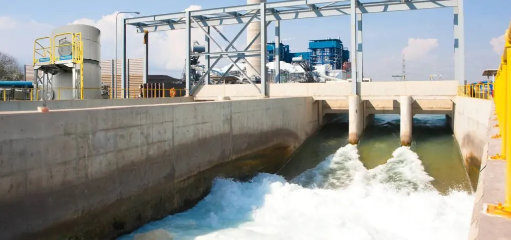
A clarifier is only as effective as the flocculation that happens upstream of it. The settling zone itself is passive — it provides residence time for gravity separation, but it cannot improve the quality of flocs that enter it. If polymer conditioning upstream is poorly designed, no amount of clarifier capacity compensates for weak, small, or poorly formed flocs.
Yet in many industrial facilities, PAM is added to clarifier systems without systematic consideration of where it is dosed, how it mixes with the incoming flow, or how it interacts with coagulants and other upstream chemicals. The result is treatment performance that falls significantly below what the clarifier and polymer combination is capable of delivering.
This guide covers the key integration decisions that determine clarifier performance with PAM — dosing point location, mixing zone design, coagulant sequencing, and multi-stage configurations — and explains how to optimize each one.
The Clarifier Treatment Train
Before optimizing PAM integration, it helps to map the complete treatment train leading into the clarifier. In most industrial applications, this includes:
Influent flow control → pH adjustment → Coagulant addition (rapid mix) → PAM addition (slow mix / flocculation) → Clarifier inlet → Settling zone → Clarified overflow
Each step in this sequence affects what happens in the next. PAM cannot bridge particles effectively if coagulant has not first destabilized their surface charge. The slow-mix flocculation zone cannot produce large flocs if the rapid-mix coagulant stage is inadequately designed. And the clarifier settling zone cannot achieve target effluent quality if flocs entering it are too small or too fragile.
Optimizing PAM integration means optimizing its position within this sequence — not just selecting the right grade and dosage.
Dosing Point Location: The Most Impactful Decision
Where PAM enters the treatment system has more influence on clarifier performance than almost any other operational variable — including dosage within the normal range.
The Optimal Dosing Zone
PAM should be introduced in a zone of moderate turbulence — enough mixing energy to distribute polymer rapidly through the incoming flow, but not so much shear that flocs are destroyed immediately after forming.
In practice, the optimal location is typically:
- In the flocculation chamber or slow-mix tank, after coagulant addition and rapid mixing
- In the inlet pipe or channel, at a point where natural flow turbulence provides mixing without high shear
- At the clarifier feed well, where turbulence from the incoming jet distributes polymer before flow enters the settling zone
What to Avoid
Too close to the clarifier inlet: Polymer does not have sufficient contact time with particles before flow enters the low-turbulence settling zone. Flocs are incompletely formed and small.
In the rapid-mix zone with coagulant: High shear in the rapid-mix zone damages polymer chains before they can bridge particles. Adding PAM here wastes polymer and reduces floc quality.
After any high-shear pump: Centrifugal pumps between the dosing point and the clarifier break formed flocs irreversibly. If a pump is unavoidable, dose PAM after the pump — never before it.
Request product samples and technical support to optimize your clarifier PAM program. → Get in touch today
Mixing Zone Design
The flocculation zone between coagulant addition and clarifier entry is where PAM forms the flocs that settling depends on. Its design directly controls floc quality.
Residence time: The flocculation zone should provide 10–20 minutes of residence time at the design flow rate. Shorter residence time produces incompletely formed flocs. Longer residence time with excessive agitation can cause floc breakage.
Mixing intensity: Agitation in the flocculation zone should decrease progressively from the coagulant addition point toward the clarifier inlet. High shear early promotes coagulant dispersion; low shear late allows flocs to grow without breakage. A two-stage flocculation design — one rapid-mix chamber followed by one or two slow-mix chambers — achieves this progression more reliably than a single chamber.
Velocity gradient (G value): For reference, typical design values are:
- Rapid mix (coagulant): G = 200–1,000 s⁻¹
- Slow mix / flocculation (PAM): G = 20–80 s⁻¹
- Near clarifier inlet: G < 20 s⁻¹
Coagulant and PAM Sequencing
The sequence and contact time between coagulant and PAM addition is one of the most frequently overlooked factors in clarifier optimization.
Coagulant must react with particle surfaces and form micro-flocs before PAM is added. If PAM is introduced too soon after coagulant — before micro-floc formation is complete — the polymer interacts with unreacted coagulant rather than particle surfaces, reducing the effectiveness of both chemicals simultaneously.
Minimum contact time between coagulant and PAM addition: 30–60 seconds of rapid mixing.
In treatment trains where coagulant and PAM are dosed at adjacent points with inadequate separation, this minimum contact time is rarely achieved. Adding a dedicated rapid-mix chamber between the two dosing points — even a simple pipe section with sufficient length for the required residence time — consistently improves performance.
For applications using ferric or aluminum coagulants for phosphorus removal or heavy metal precipitation, the required contact time before PAM addition may be longer — up to 2–3 minutes — to allow precipitation reactions to complete before polymer bridges the precipitate particles.
For guidance on coagulant and PAM combined programs, see: Meeting Wastewater Discharge Regulations with PAM
Multi-Stage Clarifier Configurations
Many larger treatment systems use multiple clarifiers in series or parallel. PAM integration strategy differs between these configurations.
Series clarifiers (primary + secondary): Primary clarifier handles bulk solids removal with high-MW anionic PAM and coagulant. Secondary clarifier polishes residual fine particles — often requiring a different, lower-dose PAM application targeting the smaller particle fraction that passed through primary treatment. Using identical polymer programs at both stages is a common suboptimal practice.
Parallel clarifiers: Identical polymer programs should be applied consistently across parallel units. Differences in dosage between parallel clarifiers — common when each unit is manually adjusted independently — produce variable effluent quality that complicates blending and compliance management. Centralized dosage control for parallel units eliminates this variability.
Recirculation systems: Some clarifier designs recirculate a portion of settled sludge back to the inlet to improve flocculation by seeding incoming flow with pre-formed floc particles. PAM dosage in recirculation systems should be based on fresh influent loading only — not adjusted upward to account for recirculated sludge, which contains previously conditioned material that does not require additional polymer.
Frequently Asked Questions
How do I know if my PAM dosing point is in the wrong location?
The clearest indicator is good jar test performance with poor full-scale clarifier results — flocs form well in the jar but not in the plant. This almost always means the full-scale dosing point exposes the polymer to shear conditions or insufficient contact time that the jar test does not replicate. Map every element between your dosing point and the clarifier settling zone and identify where shear or timing problems exist.
Should PAM be dosed before or after the clarifier feed pump?
Always after. Feed pumps — particularly centrifugal pumps — apply shear that breaks polymer chains and destroys formed flocs. PAM dosed before the feed pump arrives at the clarifier with significantly reduced molecular weight and flocculation capacity. If the pump cannot be avoided, dose PAM in the clarifier feed well after the pump discharge.
Can I improve clarifier performance without changing my PAM grade?
Often yes. Dosing point relocation, flocculation zone residence time extension, and improved coagulant-PAM sequencing frequently deliver significant performance improvement without any product change. Optimize the integration before concluding that a grade change is necessary.
Conclusion
Clarifier performance with PAM is determined as much by how the polymer is integrated into the treatment train as by which grade is selected or how much is dosed. Dosing point location, mixing zone design, and coagulant sequencing each have a direct and measurable impact on floc quality and settling efficiency.
The facilities that achieve the best clarifier performance are not necessarily those using the most advanced polymer grades — they are those that have systematically optimized every element of the treatment train from coagulant addition through to the clarifier settling zone.
If your clarifier is underperforming despite adequate polymer dosage, contact our technical team today for a free integration assessment and dosing point optimization review. → Contact our technical team today